DISCOVER MORE ...
EXECUTION
Achieving the highest quality surface extends beyond the fabrication shop to the field.
Installation is a critical component of the construction process and the CURVATUЯ™ System conveys significant advantages to the installation team. With innovative mounting hardware and the latest developments in measurement and software systems, geometrically complex facades can now be installed with unprecedented accuracy.
Since each module is factory assembled and delivered as part of a unitized system, facade accuracy is also far less dependent on field conditions.
Below is an outline of the key features supporting accurate field installation of the CURVATUЯ™ System.
EQUIPMENT
Advances in all aspects of the installation process are leveraged by the CURVATUЯ™ system to achieve a high quality surface that precisely conforms to the designers’ intent while remaining cost effective.
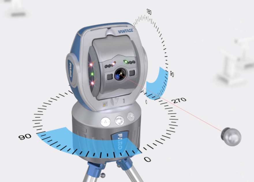
Current measurement systems offer superior levels of precision; with a range up to 250 feet (80m) and with millimeter accuracy, laser trackers such as the Faro Vantage offer fast precise positioning capabilities using sophisticated software, all in a compact portable unit.
Software developments including cloud commuting and wireless remote workstation access, provide full software capabilities on site during the installation process.
Wireless communications combined with enhanced graphics capabilities using hand held electronic devices allow field personnel to execute precise adjustments to facade units as they are installed.

LAYOUT
Complex surface geometry is almost always rendered in 3D modeling software and the architects’ surface model creates a solid foundation against which field conditions can be compared.
Measurement systems such as the Faro Vantage laser rangefinder are capable of comparing actual conditions with the model in real time. But, in order to realize the benefits inherent in this process, there must be an accurate and reliable grid system established before construction commences.
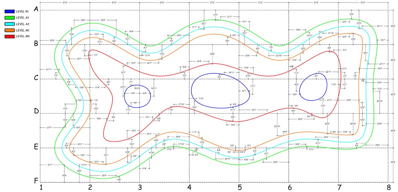
Grid systems form an essential part of modern construction layouts and the improvement in the accuracy of the facade components requires an improvement in the accuracy of the grid and measurement systems.
Strategically located concrete piers, with precision machined mounting points designed to accept a laser range finder, facilitate this improvement in accuracy.
Furthermore, the architects’ 3D model is used in the pre-construction phase to determine the optimal locations for this grid system. This grid may or may not be part of the normal rectilinear grid commonly used in construction and must be designed to the specific building geometry.
Where necessary to maintain sight lines for the measurement system, additional grid locations may be required. These should be determined prior to the commencement of construction, however if required they can be added at any time..
SET UP
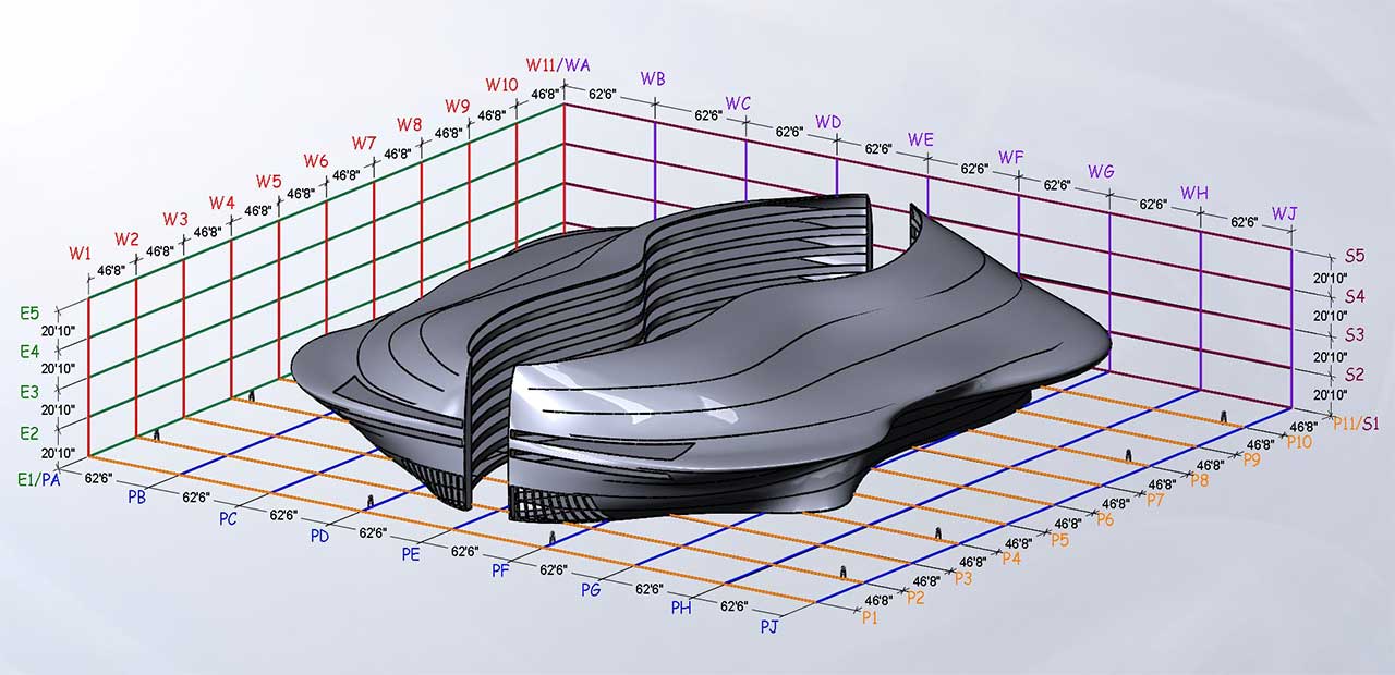
Once an appropriate grid system is designed, further investigation via 3D modeling allows the development of the sequence in which facade components will be installed.
Maintaining sight lines is a critical part of the measurement systems’ ability to locate and control panel locations in the field. Careful planning and forethought including the consideration of other trades’ work is necessary to ensure all areas of the surface can be located to the tolerances required.
Sequencing of panels and the design and location of the grid must be developed in conjunction with the overall project schedule and the construction sequence. Major components of a building, such as elevator shafts and primary structural members may limit or otherwise govern location of the measurement units and these features must be considered well in advance.
It is possible that some parts of the grid system may not be able to be established until after some aspects of the construction process has been completed. This may require the development of the grid system over time which in turn may govern areas of the facade that can or cannot be installed at those times.
New grid points may be added as required and incorporated into the 3D model in the field, in real time, if needed.
PROCESS
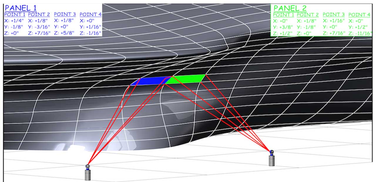
With facade components fabricated in the shop to high levels of accuracy, the number of data points that need to be captured in the field is reduced from thousands to just a few key points on each facade module.
Typically, a point cloud (tens of thousands of data points) is not required and for regular rectangular modules, only 4 corners need to be located and controlled. This greatly reduces the measurement systems’ data acquisition time on site.
Using a Spherically Mounted Retroreflector (SMR), corners are located in 3D and compared to the model in real time. Adjustments required at each corner are determined by software and transmitted to the installer wirelessly. Adjustment in the X, Y and Z directions is performed and the installation team quickly move to the next unit. This improvement in installation efficiency greatly reduces field labor and thus cost.
Modern laser measurement systems also allow for daily monitoring of the grid system to preserve the integrity of the measurement and installation process. Daily calibration of all grid locations helps ensure accuracy over time.
Once in use, the measurement system may also be used to understand and accommodate the daily movement of the building structure due to thermal cycling, the effects of dead loads and settling of the foundations etc. These variables must be monitored and understood to ensure accurate installation of the facade units.
A further advantage of the establishment of a laser grid system and the use of laser trackers lies in the ability to assist in the precise location of other major components such as HVAC, MEP and other specialist equipment.